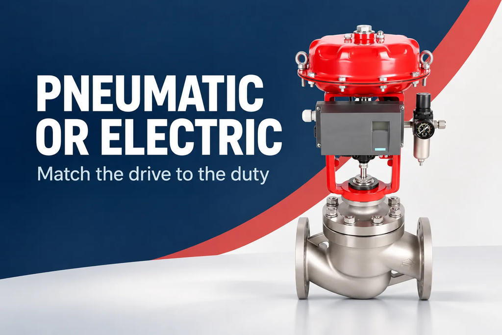
Choosing between pneumatic and electric control valves starts with the movement the process requires and the utilities available at the installation. Both approaches can support industrial automation. Their practical differences involve energy supply, operating pattern, response, interruption behavior, and integration with the control system. Neither is inherently the best choice for every regulating or isolation duty.
The comparison should use complete assemblies with the same required function. A pneumatic valve with a spring-return action is not directly equivalent to an ordinary electric valve that holds its last position after power loss. Likewise, an occasional-duty electric actuator should not be compared with a pneumatic package intended for frequent modulation without accounting for that difference.
Begin with the valve rather than the energy source
The valve’s required torque or thrust, movement, and sealing task establish the actuator load. Pressure differential, temperature, friction, and the selected trim or seat influence that load. Those requirements exist regardless of whether the final drive uses compressed air or electricity.
Define whether the duty is continuous regulation, occasional positioning, or open-close operation. A process that needs frequent small corrections places different demands on the drive than a valve that moves a few times each week. Describe the movement pattern in practical terms before selecting an energy source.
For pneumatic and electric control valves, the useful first comparison is therefore functional: can each proposed package move the selected valve, at the required frequency and speed, under the relevant conditions? Utilities and cost can then be compared against a common task.
Assess the air system that actually reaches the valve
A pneumatic actuator depends on a suitable air supply at its connection. Header pressure alone does not establish the available pressure during movement. Pipe size, tubing, restrictions, regulators, and simultaneous users can affect the pressure and flow available when the actuator needs them.
Air quality also matters to the selected equipment. The supply arrangement should fit the actuator and accessories, including the positioner or solenoid where used. A plant that already has suitable instrument air faces a different installation decision from a remote site that would need a new compressor, treatment, and distribution system.
Consider maintenance and access to the supply components. A valve package can be mechanically sound while an obstructed restriction or inadequate branch supply limits its response. The actuation system includes the path delivering the energy, not just the cylinder or diaphragm.
Assess the electrical installation just as carefully
An electric actuator needs the specified voltage, frequency, and phase arrangement where applicable. Cable routing, protection, local isolation, and controls contribute to the installation. A nearby power source may simplify the project, but the actual motor supply must remain suitable under the expected operating conditions.
Electric assemblies also have operating-duty limits. Frequent starts, reversals, load, and ambient temperature affect suitability. A design intended for modulation can address a different pattern from one intended for occasional full strokes. The word “electric” does not describe that distinction.
Separate electrical power from communication. A network interface can remain available while the motor cannot move, depending on the design. The control system should represent readiness and power-related conditions rather than assuming that a connected device is ready to operate.
Compare response at the complete assembly
Pneumatic arrangements can provide rapid movement in suitable configurations, but actual response depends on actuator sizing, air delivery, accessories, and load. Electric movement depends on motor and gear design, output speed, and the valve mechanism. Broad category claims do not establish the travel time of a particular package.
Faster is not always better. The process may need controlled movement to limit piping transients or avoid an abrupt change in flow. A regulating loop may need repeatable small corrections more than a rapid full stroke. Specify the response required by the process rather than requesting speed for its own sake.
For a hypothetical cooling loop, the important requirement might be stable position changes during varying production. For a batch isolation sequence, completion of a full stroke within a defined window may matter more. Those are different performance questions even if the valves share a nominal size.
| Decision factor | Pneumatic arrangement | Electric arrangement |
| Available utility | Suitable air pressure and flow | Suitable electrical supply |
| Movement pattern | Actuator and accessories matched to duty | Motor and controls matched to duty |
| Interruption response | Depends on spring, air storage, and configuration | Depends on stored energy and configuration |
| Feedback | Positioner, switches, or transmitters | Position sensing and control outputs |
| Installation scope | Air distribution and signal connections | Power and signal connections |
Define utility loss and signal loss separately
A spring-return pneumatic actuator can be arranged to move toward a selected state when its operating pressure is removed. The actual result still depends on the assembly, available spring output, valve load, and accessory configuration. A double-acting actuator has a different basic arrangement and may need additional provisions for a defined interruption response.
An ordinary electric actuator may remain near its last position after motor power is lost. Movement afterward requires suitable stored energy or backup. Electrical memory or a battery-supported display is not the same as energy for a full operating stroke.
Loss of the control signal is a separate event from loss of air or power. The system may remain energized while demand becomes invalid. Define the response to each relevant event and confirm that the proposed package implements it. The general term “fail-safe” does not identify the event, direction, or completion requirement.
Compare control information rather than signal stereotypes
Both pneumatic and electric packages can provide position feedback and integrate with modern control systems. A pneumatic actuator may use an electrically commanded positioner, while an electric actuator may accept discrete, analog, or digital demands. The actuator energy source does not uniquely determine the communication interface.
Choose the signals that support operation and diagnosis: demand, measured position, operating authority, readiness, and relevant faults. Keep those concepts separate. A demand value is not proof of movement, and a closed-position indication is not a direct leakage measurement.
Where detailed diagnostics are available, use them with a clear understanding of the measurement. Additional data is valuable when it helps distinguish a movement problem from a utility or communication problem. An unexplained list of device values can create complexity without improving the operator’s decisions.
Include environment and maintenance
Outdoor exposure, corrosive atmosphere, ambient temperature, and location-specific electrical requirements influence the complete package. Pneumatic systems can include electrical accessories, so an air-powered drive does not automatically remove all electrical selection requirements.
Maintenance needs differ with the chosen construction and installation. Evaluate access to the actuator, utility components, manual operation, and replacement parts. Avoid assigning a universal maintenance advantage to either category without considering the actual site and duty.
Yongsheng process control valves offers industrial valve arrangements that can be reviewed through these functional requirements. The strongest comparison explains which existing utilities and operating needs favor a particular package, while keeping the alternative’s assumptions visible.
Compare failure response as an operating sequence
Start by naming the event: loss of instrument air at the actuator, loss of motor power, loss of control signal, or loss of communications. These events can affect different parts of the package. A comparison that says only “fails closed” may leave uncertainty about which event causes movement and which conditions are assumed to remain available.
Next, describe the required movement and confirmation. The valve may need to reach a defined position within a process-specific interval, or it may be intended to remain where it is. The actuator output must be adequate for the relevant load during that response. A spring or backup source is useful only when it can perform the required task in the selected assembly.
Then define recovery. After the utility returns, does the process permit immediate remote movement, require an operator action, or follow another established sequence? The control system should reconcile the measured position with the current operating demand rather than silently assuming that the previous command remains appropriate.
Use the same sequence when comparing pneumatic and electric proposals. One alternative may include the required stored-energy response while another includes only normal powered operation. Their prices and complexity are not directly comparable until both meet the same function. This approach avoids broad technology arguments and makes the actual scope difference visible.
For routine duties, the result may be simple. For more demanding sequences, it may require additional accessories or a different actuator arrangement. The important point is that those choices follow a defined behavior. The energy source becomes part of the solution rather than a substitute for specifying what the valve must do.
Frequently asked questions
Are pneumatic actuators always faster?
No universal response time applies to the category. Pneumatic movement depends on air delivery, accessories, actuator design, and load. Electric designs also vary. Compare the actual complete assemblies against the travel and response requirements of the process.
Can an electric actuator provide a defined power-loss position?
Yes, when the assembly includes an appropriate mechanism or backup arrangement designed for that task. It should not be assumed from the presence of a battery or electronic controls. Specify the required stroke, load, response, and confirmation.
Does pneumatic actuation mean there are no electrical components?
Not necessarily. Positioners, solenoids, transmitters, and switches may use electrical power or signals. Review the complete package and installation location rather than inferring all requirements from the actuator’s primary energy source.
What should determine the choice first?
The valve load, required movement, operating frequency, response, and interruption behavior. Available utilities and installation scope then help distinguish suitable alternatives. Starting with a preferred energy source can obscure the function the assembly actually needs to perform.
Compare pneumatic and electric options as complete operating systems. That gives the project a practical choice based on its own conditions rather than a generic ranking of actuator technologies.
References
[1] AUMA. Actuators SA.
[2] Rotork. IQ3 Pro.
[3] Spirax Sarco. Control Valve Actuators and Positioners.
